
A hydraulic system that runs hot destroys hydraulic cylinder seals, degrades oil quality, and reduces pump efficiency in a compounding cycle: heat softens seals, softened seals leak, leaking seals generate more heat from internal bypass, and the extra heat further accelerates seal degradation. Hydraulic cylinder overheating — or more precisely, hydraulic system overheating that damages the cylinder — is almost never caused by the cylinder itself. It is caused by inefficiencies in the circuit that appear as heat in the oil. This guide identifies every root cause of hydraulic overheating and the fix for each.
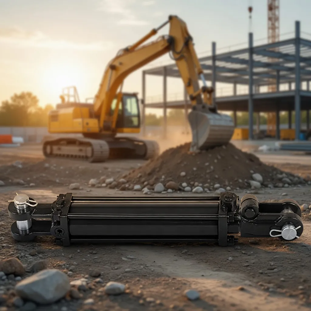
Understanding Where Heat Comes From in a Hydraulic System
Every watt of power input to a hydraulic pump that does not exit the system as useful mechanical work at the cylinder rod tip exits as heat in the hydraulic oil. The efficiency of a typical hydraulic system is 60–80% — meaning 20–40% of the input power becomes heat. At low ambient temperature and duty cycle, the reservoir surface area and oil volume absorb and dissipate this heat without the oil temperature rising significantly. At high ambient temperature, high duty cycle, or when efficiency losses increase due to component wear, heat generation exceeds dissipation and the oil temperature rises.
Relief Valve Bypassing
The single largest heat source. A relief valve set below the load pressure continuously dumps pump output to tank. All pump power is converted to heat. Symptom: oil temperature rises immediately when the cylinder is loaded; system barely moves the load.
Internal Leakage
Worn pump elements, worn valve spools, and failed cylinder piston seals all convert pressure energy to heat through internal leakage. Symptom: cylinder drifts under load; oil temperature rises progressively as components wear.
Undersized Lines and Valves
High flow velocity through undersized orifices creates pressure drop that appears as heat. Symptom: pressure drop measured across the line or valve; heat concentrated in specific section of circuit.
Metering Valve Energy Loss
Meter-out flow control valves throttle the return oil from the cylinder, converting pressure energy to heat on every stroke. Symptom: heat concentrated in the return line and reservoir; increases with cycle rate.
Diagnostic Sequence: Finding the Heat Source
Check oil temperature at startup and at 30-minute intervals. A temperature rise of more than 2–3°C per minute indicates a significant heat source in the circuit — more than the system’s thermal design accounts for.
Measure load pressure at the cylinder port under full load. Measure the relief valve setting. If the relief valve setting is within 5–10% of load pressure, the valve is continuously bypassing under load. Raise the setting by 10–15% above maximum load pressure.
A worn pump with high internal leakage generates heat while delivering less useful flow. Measure pump output at rated pressure and compare to rated flow specification. Greater than 10% shortfall indicates pump wear contributing to heat generation.
With the cylinder loaded and lines capped, observe for drift. Significant drift confirms piston seal bypass — a continuous heat source from pressure-to-heat conversion across the leaking seal.
Inspect the cooler fins for blockage with dust, chaff, or debris. Measure inlet and outlet oil temperatures — the temperature drop across a functioning cooler should match the cooler’s rated capacity at the current flow rate. A cooler that is removing less heat than the system generates must be cleaned, repaired, or upsized.
Maximum Oil Temperature by Seal Compound
| Seal Compound | Continuous Operating Limit | Peak Transient Limit | Consequence of Exceeding |
|---|---|---|---|
| NBR (Nitrile) | 80°C | 90°C | Seal softens, extrudes past gland, rapid leakage |
| PU (Polyurethane) | 90°C | 100°C | Permanent deformation, reduced seal contact force |
| FKM (Viton) | 180°C | 200°C | Correct choice for genuinely high-temperature duty |
| PTFE-Composite | 180°C | 200°C | No temperature limitation in normal hydraulic systems |
Preventing Hydraulic Overheating: System Design Practices
Hydraulic overheating is a system design issue, not a cylinder issue. Prevention starts with correct system design: set the relief valve at least 15% above maximum load pressure (not at the minimum that moves the load); size all lines and valves for maximum 4 m/s velocity in pressure lines and 2 m/s in return lines; specify an oil cooler rated for the full heat rejection load at the maximum ambient temperature; and specify the seal compound for a temperature 20°C above the maximum expected oil temperature to provide a thermal safety margin. For systems that are already overheating, contact the Ever-Power engineering team for a circuit review — identifying and fixing the heat source is always more cost-effective than upgrading the cooler to mask a circuit inefficiency.
Request a Free Specification Review
Send your application details to [email protected] or call +86-571-88220653. Our engineers respond within 24 hours.