
Specifying a hydraulic cylinder for a dump truck is one of the more geometry-intensive cylinder selection tasks in mobile hydraulics. Unlike a simple push-pull application, a tipping body involves a changing moment arm, a sequential-stage force profile, and a collapsed height constraint that is defined by the vehicle chassis design. Getting the specification wrong produces a cylinder that tips incompletely, collapses too high to fit the chassis, or generates insufficient force at the final stage when the body is at maximum angle.
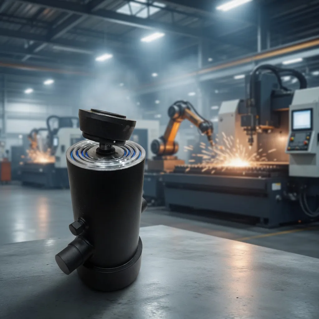
Step 1 — Determine the Total Tipping Load
The tipping load is the total weight the cylinder must lift at the beginning of the tipping stroke. This includes the empty body weight plus the maximum payload capacity. For a standard rigid dump truck with a 20-tonne payload capacity and a 4-tonne body: total tipping load = 24 tonnes = 235.4 kN. This is the force the cylinder must generate at its first stage — the outermost, largest-bore stage.
In practice, the cylinder does not lift the full load vertically. As the body tilts on its rear hinge, the effective lifting force required changes with the angle. At the start of tipping (low angle), the moment arm is greatest — this is the maximum force demand on the cylinder. At high tip angles, the load has shifted rearward and the required cylinder force decreases. The critical sizing point is the beginning of the tip cycle.
Step 2 — Calculate Required Stroke from Tip Angle
Stroke is calculated from the body geometry. With the body hinge at the rear and the cylinder mounted beneath the body at a specific fore-aft position, the stroke required to achieve the target tip angle (typically 45–55°) is determined by the geometry of the triangle formed by the hinge point, the cylinder base, and the cylinder top attachment point.
As a practical approximation for a standard 6-metre body: a 45-degree tip angle requires approximately 2,400–2,800 mm of cylinder stroke. A 55-degree angle requires 2,700–3,100 mm. These are geometry-dependent — always verify with the actual vehicle body dimensions rather than using generic approximations.
Step 3 — Determine Stage Count from Collapsed Height
The available collapsed height is the distance between the sub-frame top and the body understructure at the cylinder mounting point — typically 350–650 mm on a rigid dump truck chassis. Divide the required stroke by the available collapsed height to determine the minimum number of stages:
| Required Stroke (mm) | Collapsed Height (mm) | Stages Required | Notes |
|---|---|---|---|
| 2,400 | 600 | 4 | Typical rigid dump truck |
| 2,800 | 550 | 5 | Long body or shallow chassis |
| 1,800 | 600 | 3 | Short body agricultural trailer |
| 2,200 | 650 | 3-4 | Medium rigid truck |
Step 4 — Calculate Bore Diameter for Required Force
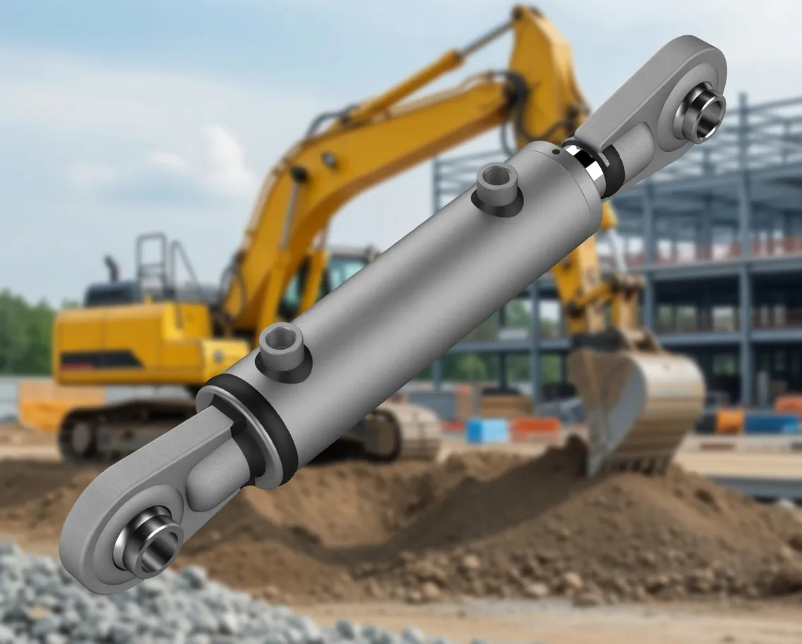
Calculate the bore of the outermost (first) stage from the tipping force and system pressure. Apply a safety factor of 1.5× to the calculated tipping force before determining bore area: Bore = 2 × √(Factored Force ÷ (π × System Pressure)). Round up to the nearest standard bore. Then calculate bore sizes for each subsequent stage — stage bore diameters decrease by approximately 5–12 mm per stage depending on wall thickness.
The critical check is the innermost (final) stage force at the maximum tip angle. At maximum tip angle, the geometric moment arm is shortest, reducing the cylinder force requirement — but the final stage bore is also smallest, reducing the available force. Confirm that the final-stage force at maximum angle is sufficient for the load at that geometry. This check catches the most common dump truck cylinder specification error.
Step 5 — Connection Type and Mounting
Standard dump truck telescopic cylinders use a flange base (bolted to the sub-frame) and a dome top (bearing against the body understructure) or a clevis top (pinned to the body frame). The flange bolt pattern and dome/clevis dimensions must match the sub-frame and body design. Provide the vehicle manufacturer’s mounting drawing or the existing cylinder’s base flange dimensions to Ever-Power when ordering a replacement or custom unit — these are the dimensions that determine whether the cylinder physically installs correctly.
Request a Free Specification Review
Send your application details to [email protected] or call +86-571-88220653. Our engineers respond within 24 hours.